

Tuesday, December 5, 2017
Melanie Martinez, Accused of Sexual Assault by Ex-Friend, Responds: ‘She Never Said No’

Singer Melanie Martinez, who rose to fame competing on season three of NBC’s “The Voice,” has been accused by a former friend of sexual assault. The alleged incident was detailed by Timothy Heller, herself an aspiring musician, who, in a four-part tweet, recounted a night during which she “repeatedly said no” to Martinez’s sexual advances. Heller accuses Martinez of forceful penetration with a sex toy, among other acts.The Los Angeles-based Heller posted the tweet just before 3 p.m. local time. Within eight hours, it was retweeted more than 50,000 times.Martinez and Heller appear to have a friendship that dates back to 2015, judging by images on social media platforms.At 11:30 p.m. Martinez posted a response on her own Twitter, writing, “I am horrified and saddened by the statements and story told by Timothy Heller. What she and I shared was a close friendship … We tried to help each other. We both had pain in dealing with our individual demons… She never said no to what we chose to do together. And although we parted ways, I am sending her love and light always.”

Sunday, November 5, 2017
Peak to Peak Voltage Calculator

This calculator shows the peak-to-peak voltage (VP-P) value from the peak voltage, RMS voltage, or average voltage.
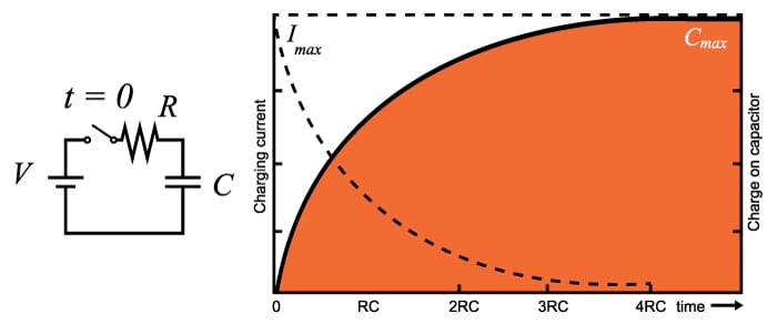
Capacitor Charge and Time Constant Calculator
This calculator computes for the capacitor charge time and energy, given the supply voltage and the added series resistance.
Outputs
Joules
seconds
Overview
This calculator is designed to compute for the value of the energy stored in a capacitor given its capacitance value and the voltage across it. The time constant can also be computed if a resistance value is given. Note that the input capacitance must be in microfarads (μF).
Equations
Where:
= applied voltage to the capacitor (volts)
= capacitance (farads)
= resistance (ohms)
= time constant (seconds)
The time constant of a resistor-capacitor series combination is defined as the time it takes for the capacitor to deplete 36.8% (for a discharging circuit) of its charge or the time it takes to reach 63.2% (for a charging circuit) of its maximum charge capacity given that it has no initial charge. The time constant also defines the response of the circuit to a step (or constant) voltage input. Consequently, the cutoff frequency of the circuit is defined by the time constant.
Applications
The charging/discharging property of a capacitor made a lot of applications in electrical engineering possible. Here are some of them:
Flash Lamp
The flash lamp of a throwaway camera is powered by the charge stored on a capacitor. The circuit of a flash lamp normally consists of a large high-voltage polarized electrolytic capacitor to store the necessary charge, a flash lamp to generate the required light, a 1.5-v battery, a chopper network to generate a dc voltage in excess of 300 V, and a trigger network to establish a few thousand volts for a very short period of time to fire the flash lamp. It should certainly be of some interest that a single source of energy of only 1.5 V dc can be converted to one of a few thousand volts (albeit for a very short period of time) to fire the flash lamp. In fact, that single, small battery has sufficient power for the entire run of film through the camera.
Surge Protector
In recent years we have all become familiar with the line conditioner as a safety measure for our computers, TVs, CD players, and other sensitive instrumentation. In addition to protecting equipment from unexpected surges in voltage and current, most quality units will also filter out (remove) electromagnetic interference (EMI) and radio-frequency interference (RFI). The filtering is done with the right combination of a resistor and a capacitor. The charging and discharging of the capacitor means it would not allow rapid voltage spikes that would otherwise harm appliances and equipment.
Inverting Op-Amp Resistor Calculator
This calculator determines the bias and feedback of resistors for an inverting op-amp.
Outputs
kΩ
kΩ
kΩ
Overview
An inverting operational amplifier (op-amp) amplifies the input signal while inverting its polarity. This calculator is designed to compute for the resistors R2, R3 and R4 given the other parameters. The resulting values are in kilo-ohms (kΩ).

Equations
Applications
The operational amplifier is a staple in electronics design as it can be found in hundreds of applications. The most common uses of the op-amp includes amplification, as buffer, as controlled source and in active filters.
Amplifier
The op-amp can be configured as a non-inverting amplifier or as an inverting amplifier. The circuits for these two amplifier configuration is shown below:
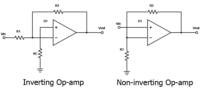
The gain of the inverting op-amp can be calculated using the formula:
,
while the gain of the non-inverting op-amp is given as:
Any of these amplifier configurations can be cascaded for greater gain. Cascading two inverting op-amps can also return the signal to its normal polarity.

